Author Topic: Cleaning up the wiring loom [XBR]  (Read 1626 times)

guest1130

  • Guest
Cleaning up the wiring loom [XBR]
« on: March 22, 2011, 10:18:31 PM »
So, I started to go through the wiring diagram to figure out which wires are useless to me so I can clean up the wiring loom a bit. Hopefully some of you have more experience reading diagrams than me so you can verify my conclusions before I cut something vital off my wiring loom..

Here's a modified picture of the XBR wiring loom. The red leads represent the ones that are no longer needed:


The way I figured it:
- The sidestand indicator and the sidestand switch are useless (and not found on my bike to start with if I recall correctly).
- The starter motor and relay are useless since this bike will be kickstart only.
- The clutch switch is no longer needed as I find it to be connected only to the starter motor relay
- The neutral indicator wiring has been partially removed, due to the fact that I like having the neutral indicator light on my instrument panel, but it no longer needs to relate to the starter relay.
- The starter switch can also be de-wired since, well, there's no starter.

Hopefully you can point out any flaws with my plans or better yet, find more stuff that can be removed!

guest1130

  • Guest
Re: Cleaning up the wiring loom [XBR]
« Reply #1 on: March 24, 2011, 02:05:20 PM »
So far,I've tried to separate each cirquit (turn signals, headlight, brakelight etc.) to see how many unnecessary wires are left. So far I've noticed a few points:

- Why on earth does the wiring loom have only one ground point?? I mean, since the bikes electrical components can easily be divided into front, center and rear I'd think it would save a lot of wire plus simplify the loom a LOT if there were several ground points and only the positive/signal leads would go through the loom. Only downside to this is that the more ground points need to be undone if ever wanting to take out the loom as a whole off the bike.

- Does anyone have any info on the "tail and brake light sensor" ? What does it do? I can only think of one function for its existence, to detect a faulty taillight. If so, will it be confused when using a LED taillight?

guest1130

  • Guest
Re: Cleaning up the wiring loom [XBR]
« Reply #2 on: April 18, 2011, 09:23:32 AM »
I'm starting to figure out how my electrics are going to be. However, I'm a bit confused with my blinkers.

The bike came with Kellerman LED indicators which weren't connected. I have read that there are specially designed relays for LED indicators so you won't haveto place a ballast resistor to each indicator wire.

My problem is connecting the blinkers, bare with me:

- Each of my new LED blinkers have three (3) wires coming out of them:
  • Black
  • Red
  • Yellow
I have no instruction manual so I have no idea on what each wire does. I'm assuming that the Black one is ground. The red wire is positive but what is the yellow wire for?

- Now if you look at the XBR wiring diagram, you notice that there are infact three wires connecting to the front indicators, but only two wires connecting to the rear indicators?

Anyone have any input on what the third wire does?

EDIT:

I'm generally BAFFLED on how the blinkers on XBR are connected, hopefully you guys have the time to help me out. The following image shows the current flow while the right turn button is pressed, check out what happens according to the XBR wiring diagram:


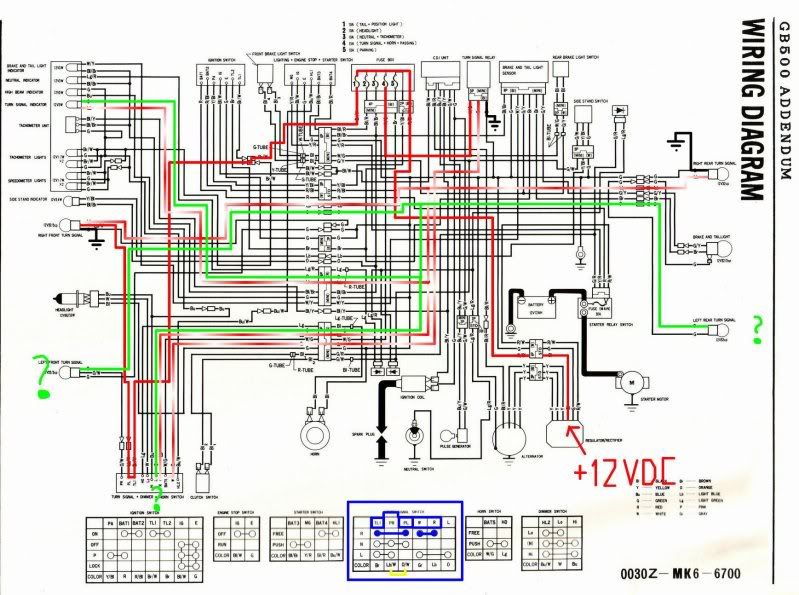
Right, now lets follow the current flow, and I really hope if you find any flaws with this you point them out!
- The positive source starts to feed continuous +12VDC (the red line) from the RECTIFIER, which I've highlighted with a red "+12VDC"
- It leads to the FUSEBOX, and goes through
  • FUSE #4, which feeds continuous +12VDC to the TURN SIGNAL RELAY
  • FUSE #1, which feeds continuous +12VDC to the terminal TL1 on the left handlebar switch
- We can tell by the CONNECTION MAP (higlighted blue), that when "turn right" is pressed, TL1 and PL terminals are connected.

NOTE: the "PL" terminal is coloured "O/W" on the connection map but actually has a "Lb/W" lead starting from it on the actual wiring diagram. This really confuses me since I now can't be sure wether I should follow the colour or the terminal name - here I'm following the terminal name.

- As TL1 and PL are connected, the continuous +12VDC is fed from FUSE #1 to the middle terminal of the RIGHT FRONT TURN SIGNAL

Here's the first WTF-moment. If continuous +12VDC is connected to the right front turn signal, and it has a solid ground connection, shouldn't it be lit permanently?

Lets now follow the second continuous +12VDC coming from the fuse #4:
- The continuous +12VDC activates the TURN SIGNAL RELAY, which has a solid ground, and pulsating +12VDC (the red/white line) is fed from the middle terminal of the relay.
- It leads to the terminal W on the left handlebar switch.
 We can tell by the CONNECTION MAP (higlighted blue), that when "turn right" is pressed, W and R terminals are connected.
- As W and R are connected, the pulsating +12VDC continues its way to:
  • RIGHT REAR TURN SIGNAL, which has a solid ground - hence starts to blink correctly
  • RIGHT FRONT TURN SIGNAL, which also has a solid ground and would start to blink corrctly. (Note the continuous +12VDC at the middle terminal - what is it for?)
  • TURN SIGNAL INDICATOR, which doesn't have a solid ground

Here's the second WTF-moment. As you follow the second lead (highlighted light green) from the TURN SIGNAL INDICATOR, you notice that it's really not going to any groundpoint, but rather to the FRONT / REAR LEFT TURN SIGNALS and the L terminal of the left handlebar switch. A bulb always needs a ground when connected to a positive lead, the only place it could get ground would be through either of the left turn signals, which would cause them to blink as well.

PHEW, that was a lot of work, hopefully some of you guys find the time to read this through and give me your opiniones on the matter.

guest1130

  • Guest
Re: Cleaning up the wiring loom [XBR]
« Reply #3 on: April 18, 2011, 02:18:49 PM »
So luckily I had not scrapped the original blinkers, and managed to take a look at them. Turns out, the XBR front blinkers only have two wires coming out... Also the left handlebar switch doesn't have O/W, Lb/W or Br/W wires coming out of it.

It appears as that this wiring diagram is not to be trusted like a rock..

guest1130

  • Guest
Re: Cleaning up the wiring loom [XBR]
« Reply #4 on: April 26, 2011, 08:09:47 PM »
Since all my LED-bulbs are polar - thus lit only if the positive and negative lead are connected the right way, I've been going thru the turn signal indicator light cirquit. The GB 500 wiring diagram suggests that the indicator light is connected to light-blue (Lb) and orange (O) wires (this is confirmed as I've taken my gauges apart and checked the wire colours) - which are connected to the positive terminals of either right side (Lb), or left side (O) turn signals' POSITIVE end. How can the indicator light ever be lit if it has no negative end (ground)???

I still haven't figured this out, and I'd really appreciate if someone smarter than me could explain this to me.

In the mean time, I've found a solution around this problem - I'll simply re-wire the indicator light - one end to ground and the other one straight to the pulsed +12VDC from the turn signal relay. This assures the indicator light will flash ALWAYS when the relay is working - no matter which direction I'm signalling to. This also excludes the indicator bulb from the actual turn signals.

guest1155

  • Guest
Re: Cleaning up the wiring loom [XBR]
« Reply #5 on: April 27, 2011, 05:23:14 AM »
3 wires could mean it has running lights. ie 1 earth 1 power in for flashy action and 1 power in for the indicators to come on and stay on. if you are cutting the loom up anyways i'd try to experiment. you should be able to build a flasher circuit on the bench using your battery, flasher unit, switchgear, indicators and some old spare wire and connectors. i'd get it to work off the bike. (battery to switch to flasher to bulb or whatever it is) then get it on the bike. I fing when rewiring a bike myself the only thing the book is good for is finding out which colour wires are supposed to be coming out of the switchgear that i want to use. for all else i'd ignore it.

hope this helps.

guest1130

  • Guest
Re: Cleaning up the wiring loom [XBR]
« Reply #6 on: April 27, 2011, 08:24:42 AM »
i experimented last night with the flashers and figured out the third wire - The black one is ground, the red one is to power up the six red LED's inside the flasher and the yellow one is to power up the rest of the LED's, which are yellow. Power up the yellow AND the red LED's and tadaa : you get orange light :D ! This of course gives the option to extend my brake light to the red zones of the rear turn signals, which might look good.

As for the cirquit of the turn signal indicator on the gauge cluster, my initial plan doesn't work since the relay has continuous +12VDC and ground. If I were to simply connect the indicator light to the pulsed +12VDC, it would be flashing all the time. I think I need some diodes to redirect the positive and negative current to my liking...